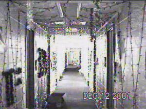
A screenshot from the above-linked video.
To improve on my past Christmas light display I decided to work on two different aspects. First, more individual segments were needed, that way high-resolution effects could be created. Also dimmable segments would increase the utility of the hardware and allow for many new patterns and designs to be created.
As I worked on prototypes some of the details of the design fleshed out. Using optoisolated triacs I was able to independently dim 6 different channels using a single PIC microcontroller occupying about only 50% of the processor's execution time and still guaranteeing 64 levels of brightness. Therefore each of my boxes would dim 6 channels.
Also I thought that increasing the number of controllable segments by 6 times was a good target to shoot for. With that many more segments, the old connection scheme of a separate wire from the master to each segment would be infeasible. I decided on a multi-drop serial bus to simplify wiring. The PICs do not have a built in UART, and at the speeds necessary for good patterns a software UART would not be possible. Therefore I used MAX3100 SPI UARTs from Maxim, along with 485 transceivers also from Maxim.
Since 20 boxes would be needed to support the 120 channels, manual assembly on perfboard was also not very possible. To expedite the assembly and make it so that others could help, a printed circuit board was designed and printed. With around 6 people working continuously, 21 boxes took about 30 hours to assemble and test.
The interface to a PC was implemented by a separate 232-485 transceiver using a MAX3110, MAX3100 and a PIC. One of these was used for each wing, so each transceiver drove only 10 boxes. Logic power was also provided to all the connected boxes through this interface. The PCs connected to the transceivers listened on a network socket for pattern data, writing out everything it received to the serial port. By these means one central computer controlled all 120 channels in the hallway.
The patterns were all implemented as an xmms visualization plugin. About half of the patterns were in sync with the currently playing music, while the other half were just geometric patterns. For the demonstration, large speakers were set up in the center of the hallways such that they could be heard from any point.
Thanks in part to the light display, 4 North once again won the annual Deck the Halls competition.
A screenshot from the above-linked video.
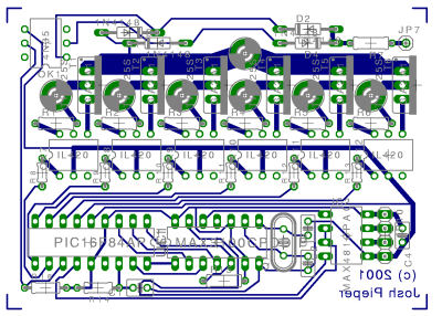
A top-down view of the circuit board with all chips shown.
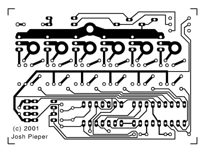
Printed circuit board etch pattern.