Blurry picture of the back side of the PCB.
For Solar Miner III we switched to using a lithium-ion based battery pack as opposed to the lead acid batteries we had used in prior projects. The new chemistry required the use of many small cells, each of which was prone to failure due to electrical stress. After our manufacturer supplied protection circuits were deemed inadqeuate we decided that some system of monitoring the cell voltages in our battery pack was necessary for the safety of the car and driver. I designed the following circuit to meet these needs.
The system had the following constraints:
To meet the accuracy requirements over all cells, I decided to optically isolate 1 A/D for every 3 cells. All the A/Ds used a common SPI (Serial Peripheral Interface) bus, so that control lines were reduced.
The data acquisition side of the opto-isolators was driven by simple combinatorial logic and a tri-state driver. Power for this side came from the main car DC/DC converter. The A/D side of the optoisolators was powered by an ultra-low quiescient current 5V regulator connected across the three cells being measured. This did introduce static power draw, but was necessary to achieve isolation. It was calculated that over the course of the entire 10-day race this static draw accumulated to less than 2 Watt-hours.
I also designed prototypes on perfboard, but due to the tight space requirements manufacturing the 9 required for the car was too difficult. Eventually we decided to have a PCB run done to help finish things up. I did not create the artwork for this board, but the basic layout is based off of my original prototype.
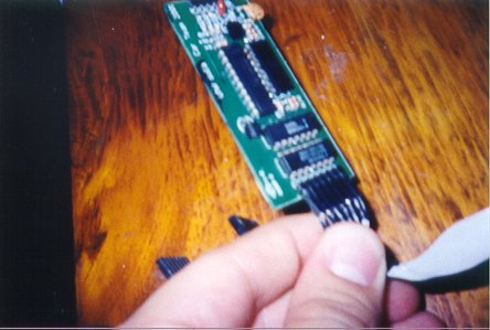
Blurry picture of the back side of the PCB.